UNDOCUMENTED THINGS….
The Expander 80 allows every parameter to be controlled by MIDI controllers, though Siel never told you what they were, so here they are:-
|
Param
|
Function
|
MIDI CC
|
Range
|
Param
|
Function
|
MIDI CC
|
Range
|
|
|---|---|---|---|---|---|---|---|---|
|
01
|
DEG VCA-A Attack
|
12
|
0 ~ 15
|
36
|
DEG VCF Release
|
38
|
0 ~ 15
|
|
|
02
|
DEG VCA-A Decay
|
13
|
0 ~ 15
|
37
|
DEG VCF Dynamics
|
39
|
0 (Off), 1 (On)
|
|
|
03
|
DEG VCA-A Breakpoint
|
14
|
0 ~ 15
|
41
|
LFO-2 Freq
|
40
|
0 ~ 15
|
|
|
04
|
DEG VCA-A Slope
|
15
|
0 ~ 15
|
42
|
LFO-2 Final Lvl
|
41
|
0 ~ 15
|
|
|
05
|
DEG VCA-A Sustain
|
16
|
0 ~ 15
|
43
|
LFO-2 Initial Level
|
42
|
0 ~ 15
|
|
|
06
|
DEG VCA-A Release
|
17
|
0 ~ 15
|
44
|
LFO-2 Delay Time
|
43
|
0 ~ 15
|
|
|
07
|
DEG VCA-A Dynamics
|
18
|
0 (Off) ~ 1 (On)
|
45
|
LFO-2 Delay Mode
|
44
|
1 (Man), 2 (Auto)
|
|
|
08
|
DEG VCA-A Damper
|
19
|
0 (Off) ~ 1 (On)
|
46
|
LFO-2 Wave
|
45
|
1 (Triangle), 2 (Square)
|
|
|
09
|
DCO Mode
|
20
|
1 (Whole) ~ 2 (Double)
|
51
|
LFO-1 Frequency
|
46
|
0 ~ 15
|
|
|
11
|
DEG VCA-B Attack
|
21
|
0 ~ 15
|
52
|
LFO-1 Final Level
|
47
|
0 ~ 15
|
|
|
12
|
DEG VCA-B Decay
|
22
|
0 ~ 15
|
53
|
LFO-1 Initial Level
|
48
|
0 ~ 15
|
|
|
13
|
DEG VCA-B Breakpoint
|
23
|
0 ~ 15
|
54
|
LFO-1 Delay Time
|
49
|
0 ~ 15
|
|
|
14
|
DEG VCA-B Slope
|
24
|
0 ~ 15
|
55
|
LFO-1 Delay Mode
|
50
|
1 (Manual), 2 (Auto)
|
|
|
15
|
DEG VCA-B Sustain
|
25
|
0 ~ 15
|
62
|
DCO Waveform
|
51
|
0 (Off), 1 (Sqr), 2 (Saw)
|
|
|
16
|
DEG VCA-B Release
|
26
|
0 ~ 15
|
63
|
DCO Sawtooth Octave
|
52
|
1 (16′), 2 (8′), 3 (4′)
|
|
|
17
|
DEG VCA-B Dynamics
|
27
|
0 (Off) ~ 1 (On)
|
64
|
DCO Square 16′ Level
|
53
|
0 ~ 15
|
|
|
18
|
DEG VCA-B Damper
|
28
|
0 (Off) ~ 1 (On)
|
65
|
DCO Square 8′ Level
|
54
|
0 ~ 15
|
|
|
21
|
Detune Interval
|
29
|
0 ~ 61
|
66
|
DCO Square 4′ Level
|
55
|
0 ~ 15
|
|
|
22
|
Detune Fine
|
30
|
0 ~ 15
|
67
|
DCO Square 2′ Level
|
56
|
0 ~ 15
|
|
|
23
|
Noise Level
|
31
|
0 ~ 15
|
71
|
VCF Cutoff
|
57
|
||
|
24
|
Noise Destination
|
32
|
1 (VCA) ~ 2 (VCF)
|
72
|
VCF Resonance
|
58
|
0 ~ 15
|
|
|
31
|
DEG VCF Attack
|
33
|
0 ~ 15
|
73
|
VCF Keyboard Track
|
59
|
0 (Off), 1 (Half), 2 (Full)
|
|
|
32
|
DEG VCF Decay
|
34
|
0 ~ 15
|
74
|
VCF DEG Trigger Mode
|
60
|
1 (Single), 2 (Multi)
|
|
|
33
|
DEG VCF Breakpoint
|
35
|
0 ~ 15
|
75
|
VCF DEG Level
|
61
|
1 (Manual) ~ 2 (Auto)
|
|
|
34
|
DEG VCF Slope
|
36
|
0 ~ 15
|
81
|
Chorus
|
62
|
0 (Off), 1 (On)
|
|
|
35
|
DEG VCF Sustain
|
37
|
0 ~ 15
|
82
|
Volume
|
63
|
0 ~ 15
|
If the Expander 80 ever displays 4c at switch on, this means the internal backup battery has gone.
Parameter 94 – not shown on the panel, selects the Pedal destination, 1: modulation trigger, 2:Program Up, 3: Sequencer Start/Stop (OK – the manual does mention this)
Parameter 95 selects the sequencer clock, 0: Internal, 1: External
Parameter 96 turns the metronome on, 0: Off, 1: On
MIDI Controller 65 is the Manual LFO trigger control, this is a hang over from the DK80 keyboard version, that had a trigger switch (rather than a mod wheel). Controller 65 is usually the second pedal function (although perhaps the standard controller CC1 would have made more sense – never mind…..)
The Expander 80 also responds to controller 125 (Omni On), controller 124 (Omni Off) and controller 123 (All Notes Off).
The three envelopes share the same timings, the Attack and Decay times are variable from 30mS to 6 seconds. This minimum 30mS attack time explains why the Expander 80 does not have an aggressive punchy sound. The Slope and Release times go from 60mS to 21 seconds, which should be adequate for everything.
The two LFO’s share the same spec as well, both ranging from 0.25Hz at it’s slowest to 10Hz fastest. The delay time variable from zero to 1.5 seconds. The LFO trigger mode is always Single (the Trigger Mode parameter 74 does not affect the LFO trigger). The LFO’s are not key synced, so free run at all times. In case your curious, here is the LFO speed reference:
|
LFO Frequency Setting
|
LFO Frequency
|
LFO Frequency Setting
|
LFO Frequency
|
|
|
0
|
0.25 Hz
|
8
|
3.5 Hz
|
|
|
1
|
0.5 Hz
|
9
|
4 Hz
|
|
|
2
|
0.75 Hz
|
10
|
4.5 Hz
|
|
|
3
|
1.25 Hz
|
11
|
5 Hz
|
|
|
4
|
1.5 Hz
|
12
|
6 Hz
|
|
|
5
|
2 Hz
|
13
|
6.5 Hz
|
|
|
6
|
2.5 Hz
|
14
|
8 Hz
|
|
|
7
|
3 Hz
|
15
|
10 Hz
|
RELIABILITY
Do they ever go worng? Well yes they do, but so do many vintage synths, the most common problem seems to be the power supply itself, whether they just get lost or blow up is unclear, but many Expander 80’s don’t have the original power supply, and Expander 80’s often turn up without any power supply. The power supply needs to be AC (not DC) and has to be centre tapped 16-0-16 (anything from 15-0-15 to 18-0-18 is OK, but don’t go above 18v as an unregulated line is connected to the display). The transformer needs to be 1A and connected to a 5 pin (Domino) DIN socket with the middle pin being the common (ground) and the outer pins carrying the AC.
Battery failure is likely by now if it hasn’t already been changed, although a standard CR2032 is needed it uses a soldered in holder, so a soldering iron is needed to change it.
TWEEKS.
I am not a fan of modifying things, a synth is what it is, if it’s not what you want – get a differenent one! So, consider this as calibration. The resonance on the filter is not normally set very aggresive. Remember that on the Expander 80, the VCF comes after the VCA, so if the VCF goes into self oscillation, nothing will stop it sounding. Though, the resonance can be optimised by a single internal adjustment. This needs to be done with the Expander 80 apart and switched on, there is no great danger in this, as the Expander 80 does not have any mains inside, the highest voltage is the 16-0-16 AC input, but take care you could still harm the Expander 80.
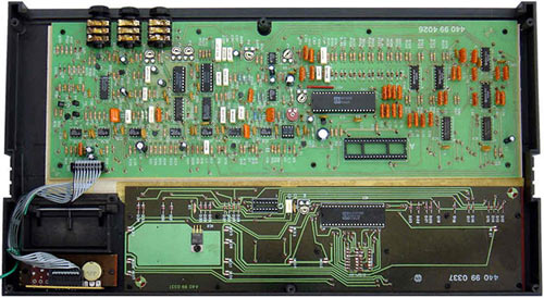
Here is a step by step guide to getting the filter resonance optimised. First disconnect the Expander 80, turn it upside down on a soft surface. Take out the 6 screws at the edges (you’ll need a thin philips screwdriver to reach into the deep recess). The next stage is to loosen the three output jack socket nuts (out L,R and phones), you don’t need to take the nuts off, but you can if you prefer. With the Expander the right way up, gently part the two halfs so that the hinge action is to the front. You will be able to lay both halves flat side by side.It should look like this:
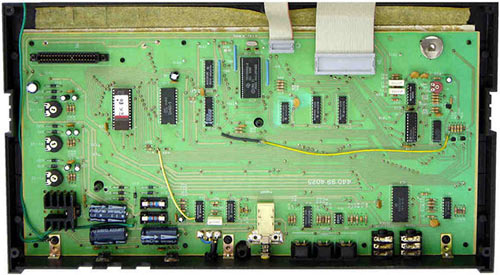
Now having laid it all out nicely, you are going to need to lift the front up so you can operate it. Connect an audio out so you can hear what’s going on and apply the power, you don’t need MIDI for this adjustment. Set the VCF cutoff to around 60 (if it’s too high you won’t hear it), set the resonance to maximum 15 (this is vital). Now locate the internal resonance adjuster P4, this is located at the back and centrally on the analogue board (the one with the output sockets on). With a small flat blade screwdriver adjust P4 slowly until you here the filter self oscillate, then back it off slightly so you cannot hear it. That is it! Put it all back together it’s done. You will find the presets sound better, and that filter will really zap now – it’s an SSM 2045 filter, so it should sound as good as this.
PEDIGREE
The oscillators/VCA’s are the M112 chip, perhaps not pedigree, as this chip was designed for use in organs, but the SSM filter is the SSM2045 as used in the Emu Emulator II, and SSM filters (mainly the SSM 2044) are used in the Fairlight CMI II, Korg Poly-6/Monopoly, PPG Wave 2.2/2.3, Kawai K3/SC240 and Simmons SDS5 etc. The early Sequential Prophet V’s used SSM 2040’s as well as the RSF Kobol.