 The MKS-30 Planet S is commonly referred to as a rackmount JX-3P. The MKS-30 has several advantages over the JX-3P, including simultaneous use of the PG-200 programmer and MIDI, a cartridge slot for storing an additional 64 patches, and velocity response.
The voice architecure is identical to the JX-3P. The two digitally clocked oscillators use a master clock which is divided by an even integer to achieve the desired pitch. The two oscillators can be synced together or cross modulated using the METAL setting. The filter module is the same one featured in the Juno 106, and has both a resonant low pass filter and a variable nonresonant high pass filter. Only one shared envelope is available for VCA and VCF. The LFO provides sine, square, and sample and hold waveforms, and has variable rate and delay.

To simulate pulse width modulation on the MKS-30 select osc SYNC, route LFO to osc 2, and turn the MIX to 100% osc 2.
To reintialize the first 32 patches in the MKS30 press and hold the WRITE button followed by the BANK button. The display will read COPY as the patches are copied into the first 32 RAM locations.
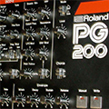
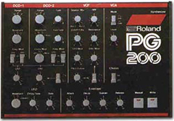
The PG-200 is a programmer for the JX-3P and the MKS-30. Since those instruments were some of the first from Roland to come out with digital parameter access for editing, as opposed to sliders and knobs, Roland made the PG-200 available. The PG-200 also works with Roland’s GR-700 Guitar Synth. It controls all editable parameters of the JX-3p and MKS-30 analog synthesizers. It was built with clunky, durable components..


Modifications
The Roland MKS-30 Operating System Upgrade was written by Johannes Hausensteiner and adds many great features to the MKS-30. Email Johannes for current pricing and availability. The added features include:
- Key Window Function
- #52 Key Window Note
- #53 Key Window Mode
– Specify note number (0..99)
Only note numbers 0 to 99 are supported from the front panel.– Below (-) or above (+)
Will playback notes above or below the split point defined in parameter #52. - Chorus Speed
- #48 Chorus Switch
- #35 Chorus Speed
- #51 Footswitch Mode
– Chorus on/off
– Only applies if hardware modification has been completed.
– Hold (-) or Chorus Speed (+)
Allows “hold” switch to alter chorus speed. - Preset Patches
- CARTRIDGE Button
- Overwrite
- Note:
– The cartridge button cycles through the patches: Main -> Cartridge -> Preset -> [Repeat].
– Press the BANK button while holding the WRITE button. Display will read “COPY” and patches 1-1 through 4-8 will be overwritten.
If no cartridge is installed, presets will be mapped to MIDI program change numbers 64 – 96. If cartridge is installed, presets are not available via MIDI program change.
- MIDI Commands
- Data Entry
- Volume
- Data Increment
- Data Decrement
– MIDI Controller #06
– MIDI Controller #07
– MIDI Controller #60
– MIDI Controller #61
– The Key Window function allows you to specify a split point and only MIDI notes above or below that split point will be played by the MKS-30. This function adds two new parameters for each patch:
– Chorus speed is now adjustable and programmable. The high pass filter must be sacrificed to enable this feature. Chorus speed can be assigned to the “hold” switch allowing realtime MIDI control. Chorus now has three programmable parameters:
– There are 32 patches in the ROM of the MKS-30. Although it is not documented in the user manual, it is possible to copy them to patch memory. To access these ROM patches with the upgrade:
– There are four new MIDI continous controllers now recognized by the upgrade:
Software – To enable the upgrade you will need to install a new EPROM chip into MKS-30. This is included with the kit. Replace the original EPROM located in socket IC46 of the MKS-30 main board with the new EPROM.
- EPROM Revision Level
- EPROM Revision Date
– To retrieve the firmware revision level press the MIDI and DYNAMICS buttons simultaneously.
– To retrieve the firmware revision date press MIDI and DYNAMICS once more.
Hardware Changes – To take advantage of the variable chorus speed feature of the new operating system, you must perform the following hardware modifications:
- Locate optocoupler P873 on MKS-30 main board. It is a black cylinder approximately 7mm in diameter by 12mm long with four wires, two on the left side and two on the right side.
- Desolder and lift the left two wires of the optocoupler. (while facing the front of the unit)
- Insert a 820k resistor in place of the two left pins of P873. This will fix the cutoff frequency of the high pass filter.
- Desolder and lift the left side of 22k resistor R42. This will separate the buffer amp for the optocoupler from the audio signal.
- Connect the two free ends of the optocoupler to both ends of 27k resistor R27 on Chorus/PS board. For best servicibility install a connector on the optocoupler side. This connects the optocoupler to the LFO of the chorus.
- Replace 47nF capacitor C13 on Chorus/PS board to 220nF. This will shift the chorus LFO center frequency and frequency range.